Quick Links

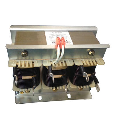
Series Reactor
A series reactor is an inductive component used in power systems, typically connected in series with capacitors. Its primary functions include current limiting, harmonic suppression, capacitor protection, and improving system stability. Below is a detailed introduction to series reactors:
1. Key Functions
- Inrush Current Limiting:
When capacitors are energized, high-frequency inrush currents can occur. Series reactors suppress these currents, protecting capacitors and switching devices.
- Harmonic Suppression:
The reactor and capacitor form an LC series circuit, tuned to specific frequencies (e.g., 5th or 7th harmonics) to block harmonic currents and prevent amplification.
- Enhancing System Stability:
In reactive power compensation devices (e.g., SVG, SVC), reactors balance system impedance and reduce voltage fluctuations.
2. Key Parameters
- Reactance Ratio (%):
The ratio of the reactor's inductive reactance to the capacitor's capacitive reactance. Common values include 5% (for suppressing 5th and higher harmonics), 6% (for inrush current limiting), and 7% (for 3rd harmonic mitigation).
- Rated Current & Voltage:
Must be selected based on system capacity and harmonic conditions to avoid overload.
- Quality Factor (Q):
Reflects the reactor's loss characteristics; low-loss reactors (high Q) are generally preferred.
3. Typical Applications
- Reactive Power Compensation:
Combined with shunt capacitors to form "filter branches," such as FC (filter capacitor) or TSC (thyristor-switched capacitor) systems.
- Inverter/Rectifier Systems:
Suppresses harmonics on the DC side, reducing grid interference.
- Renewable Energy Systems:
Used at the output of wind or PV inverters to filter high-frequency harmonics.
4. Selection Considerations
- Harmonic Analysis:
Measure the system's harmonic spectrum first, then select an appropriate reactance ratio (e.g., 4.5%~5% for dominant 5th harmonics).
- Installation Method:
Dry-type (air-cooled) or oil-immersed (for high-capacity applications), considering heat dissipation and space constraints.
- Overload Capability:
In high-harmonic environments, the reactor must withstand overcurrent conditions.
5. Common Issues & Solutions
- Overheating:
May be caused by excessive harmonic currents—check if the reactance ratio matches or if harmonics exceed limits.
- Abnormal Noise:
Caused by loose iron cores or magnetic saturation; high-quality core materials (e.g., amorphous alloy) should be used.
- Capacitor Damage:
Improper reactor selection may cause resonance—recalculate the tuning frequency.
6. Comparison with Other Reactors
- Shunt Reactor:
Used for reactive power compensation in long transmission lines or limiting power frequency overvoltages, connected in parallel.
- Current-Limiting Reactor:
Used for short-circuit current suppression, typically installed in series with busbars or lines.
Proper selection and installation of series reactors are critical for power system safety. For specific applications (e.g., design formulas, case studies), further consultation with manufacturers or engineering experts is recommended. Let me know if you'd like to explore any aspect in more detail!
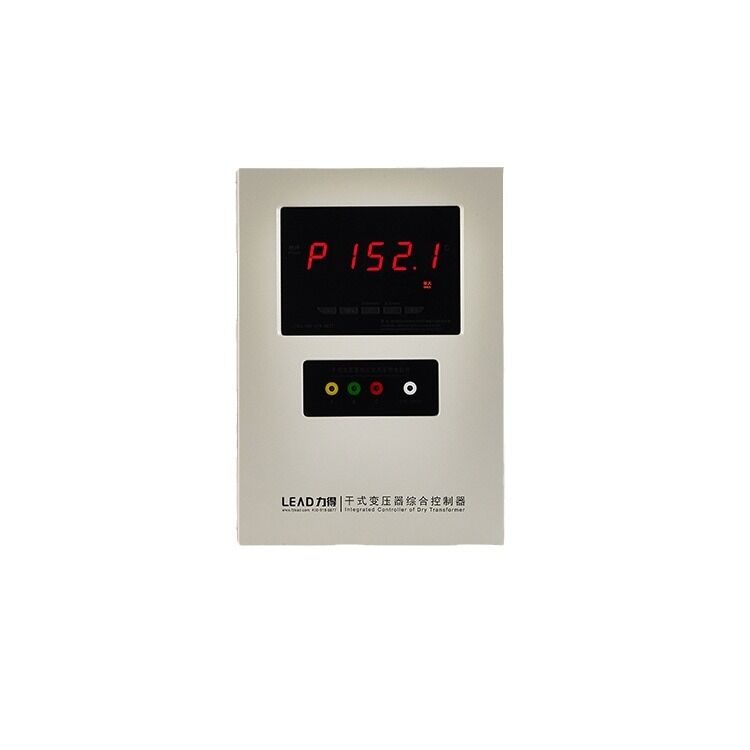
BWDK-3206H Temperature Controller of Dry BWDK-3206H
BWDK-3206A Temperature Controller of Dry BWDK-3206A
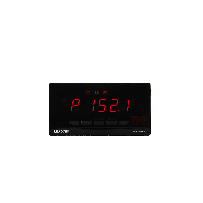
Temperature Controller of Dry LD-B10-10F
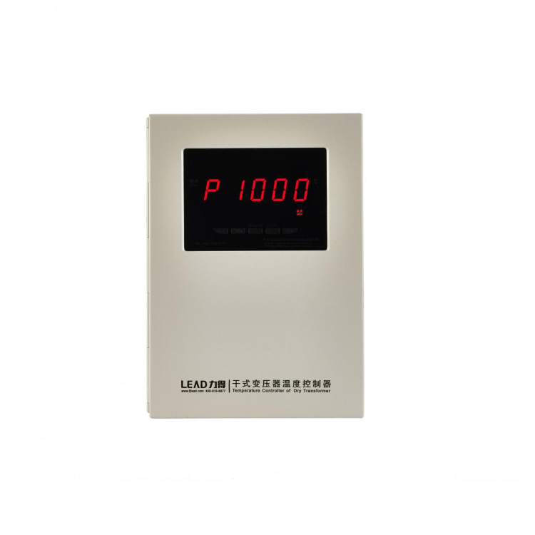
LD-B10-220 Temperature Controller of Dry LD-B10-220