Quick Links

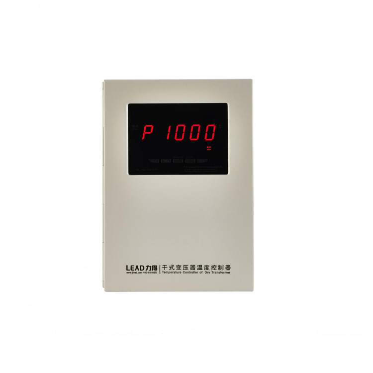
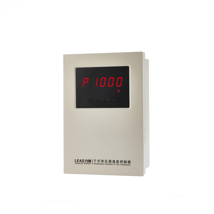
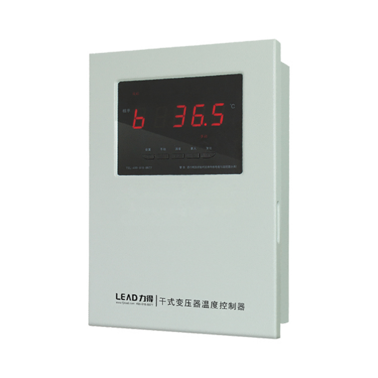
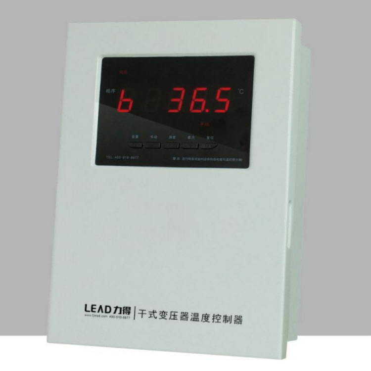
Temperature monitoring of dry-type transformer: three-phase circuit measurements and display; the maximum display; input open circuit and failure self-inspection display and output; cooling draught fan manual/automatic start-stop display and output; over-temperature alarms, over-temperature trip display and output; displayed value compensation of all channels; "black box"; control for timing start-stop of the draught fan; Temperature simulation. The full series uses the principle of number uniqueness to define input& output terminal functions, in order to facilitate the client drawing design, field wiring and control box change. Communication/simulation current is output from the terminals, no need to the intermediate conversion terminal.
Type selection (arbitrary combination of E, F, G/I and C)
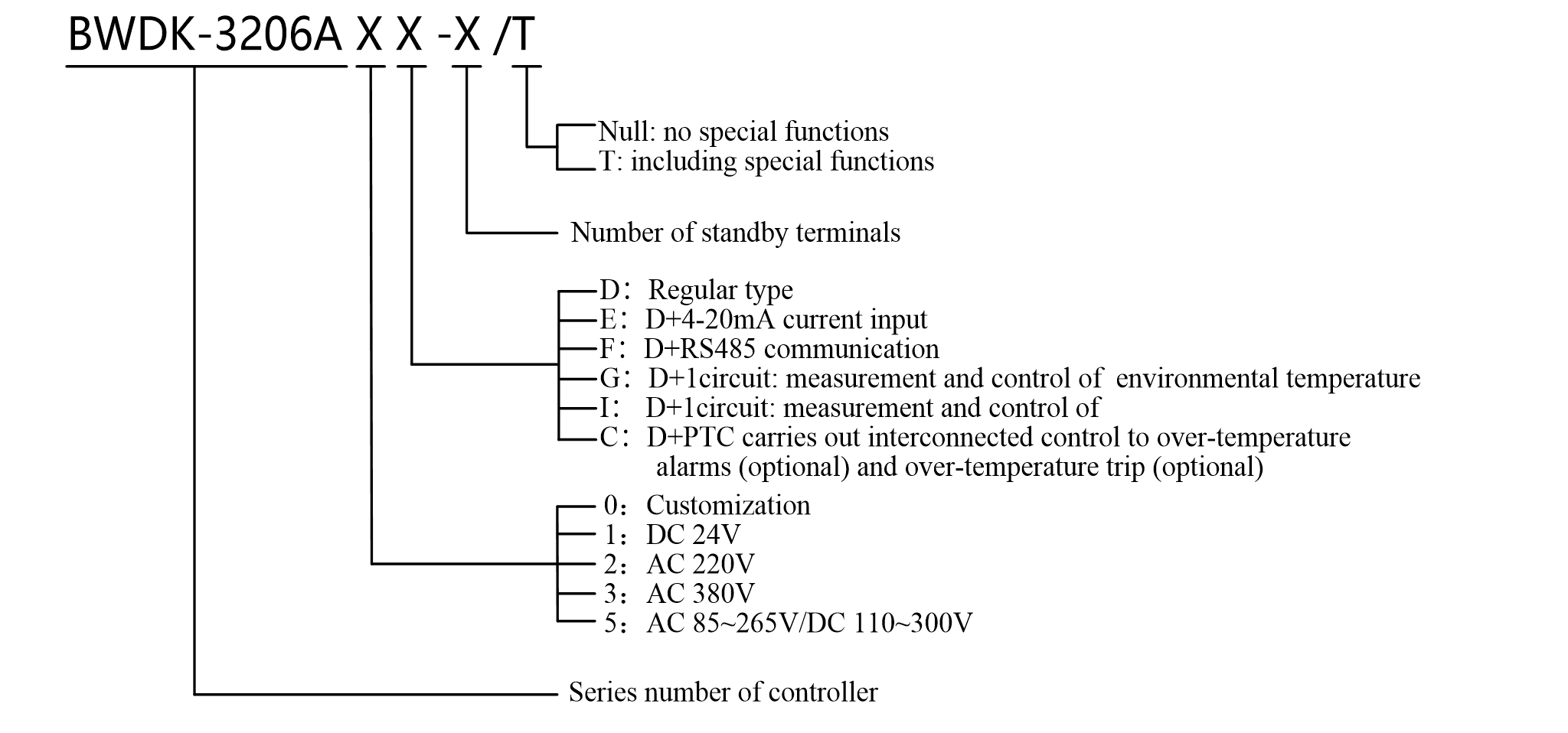
Note: BWDK-3206 series are not applicable to the same utilization of G-type and I-type.
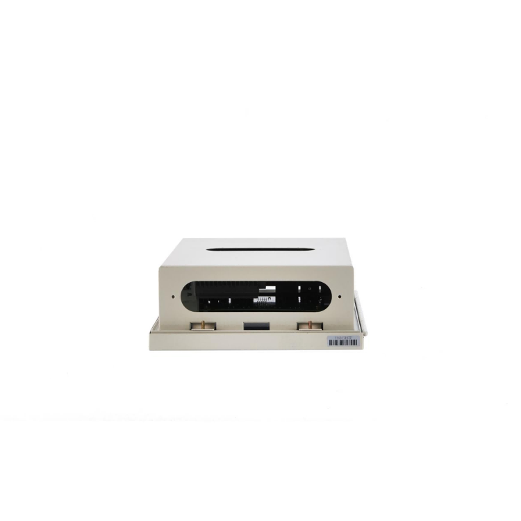
Installation instructions (inserted installation)
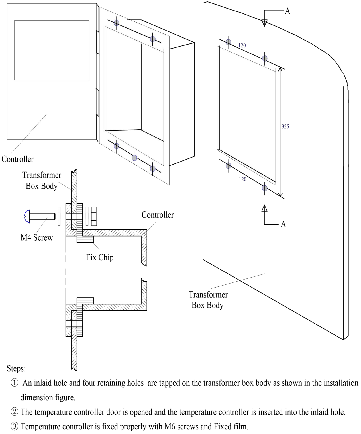

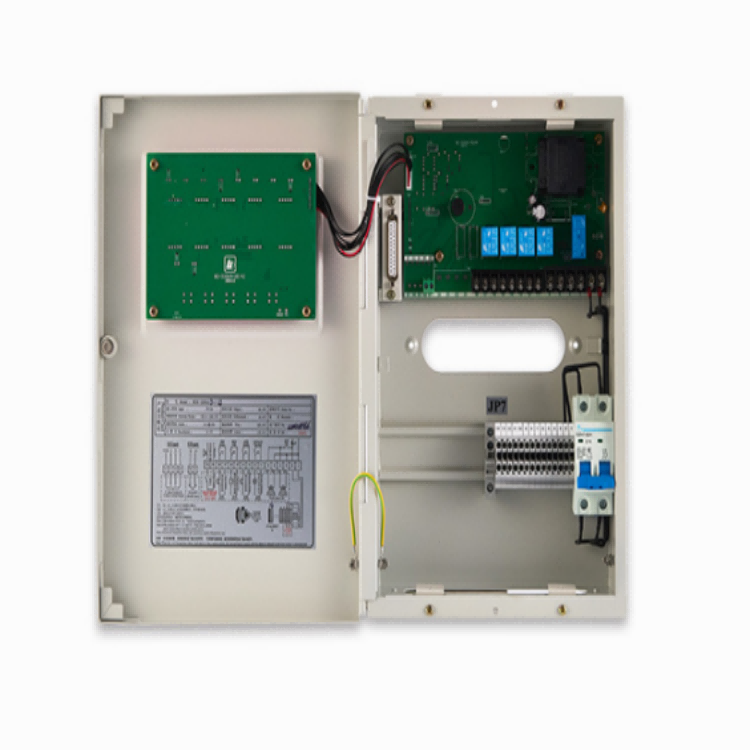
Notes: The terminal with "JP7" and without cables is a standby terminal. There is no definition for the standby terminal. l
Terminal 1 and 2 are controller working power supply and connected to AC220V (please indicate in orders if any special things exist).
Terminal 3, 4, 5 and 6 are draught fan active output. Users cannot use outer power supply when connecting the draught fan.
Terminal 11 and 12 are signal output of far eastone of draught fan (passive contact).
Terminal 13 and 14 are over-temperature alarm output (passive contact).
Terminal 15 and 16 are over-temperature trip output (passive contact).
Terminal 17 and 18 are fault alarm output (passive contact).
Terminal 51 and 52 are door contact signals input (do not use the outer power supply because of internal power supply).
Terminal 53 and 54 are RS485 communications (F-type functions). l The model and number of standby terminals are remarked when users order goods.
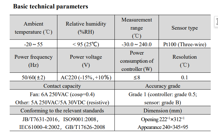
Product data sheet
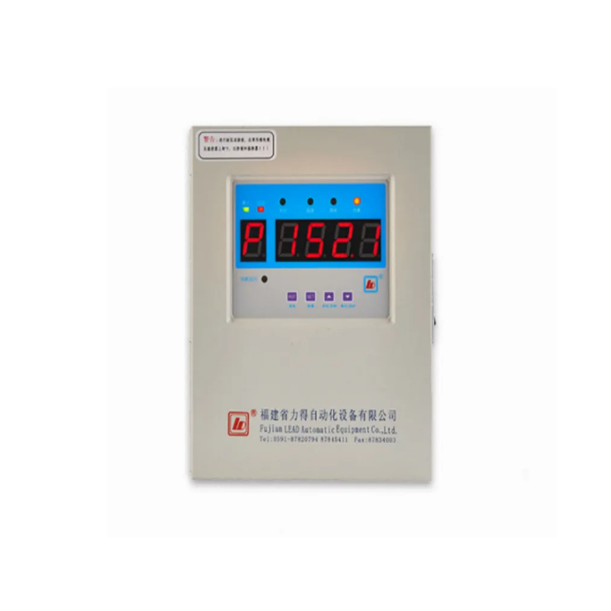
LD-B10-220 Temperature Controller of Dry LD-B10-220
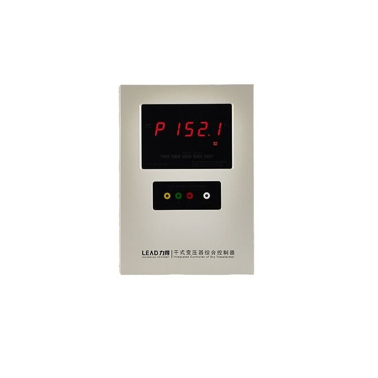
BWDK-3206H Temperature Controller of Dry BWDK-3206H
BWDK-3206A Temperature Controller of Dry BWDK-3206A
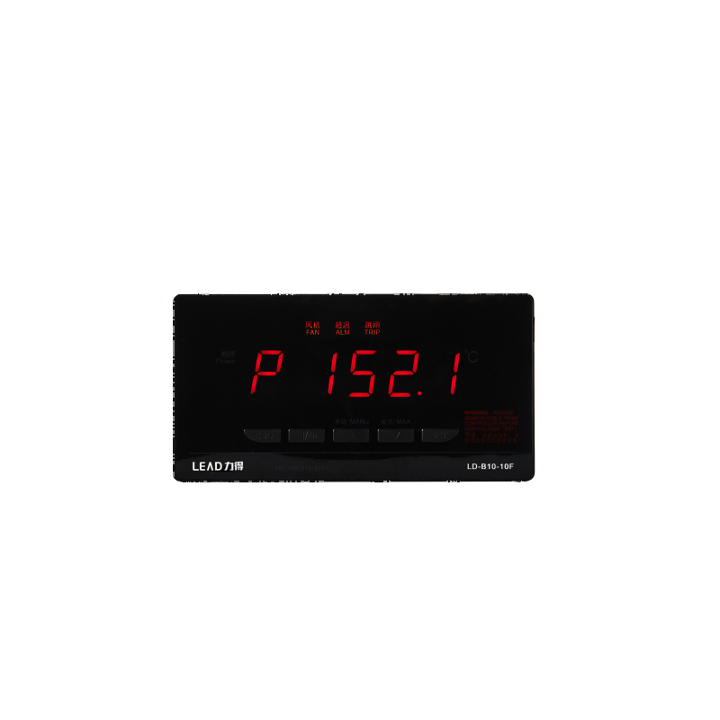
Temperature Controller of Dry LD-B10-10F