Quick Links

Here’s the professional English translation of your product description for the Output Reactor (or Output Choke) :
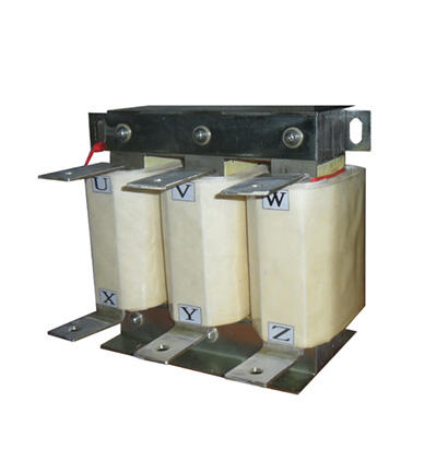
Product Overview
This product is an output reactor (also known as a variable frequency drive (VFD) output reactor or motor side reactor ), designed for installation between the VFD and motor to address electrical issues caused by long cable runs or complex operating conditions. Below is a detailed breakdown of its key features:
Key Functions
1. Suppresses Voltage Transients (dv/dt)
Reduces high frequency voltage spikes caused by PWM switching, protecting motor insulation and preventing breakdown due to rapid voltage changes.
2. Reduces Eddy Current Losses & Harmonic Effects
Filters out higher order harmonics (especially 5th, 7th, and 11th), minimizing core and copper losses in motors, improving efficiency, and extending motor lifespan.
3. Minimizes Leakage Current & Electromagnetic Interference (EMI)
Mitigates high frequency harmonics induced leakage currents through cable parasitic capacitance, reducing interference with nearby equipment.
4. Noise Suppression
Smoothens current waveforms, decreasing motor vibration and electromagnetic noise caused by harmonics.
5. Protects VFD Power Devices
Limits current surges, reducing stress on IGBTs and other switching components, enhancing system reliability.
Typical Applications
1. Long Cable Runs
Required when the cable length between the VFD and motor exceeds 50–200 meters (exact distance depends on VFD model and cable parameters) to compensate for distributed capacitance effects.
2. Poor Power Quality
Ensures system stability when the power supply has voltage imbalance (>1.8% of rated voltage) or high frequency interference .
3. Low Impedance Power Supply
Essential when the Transformer capacity is 10 times higher than the VFD’s rated power, as the reactor limits short circuit current impacts.
4. Multiple VFDs or Power Factor Correction (PFC)
Prevents harmonic amplification in shared lines with multiple VFDs and avoids resonance with ower factor correction capacitors (cosΦ compensation).
Selection Guidelines
Cable Length : Longer cables require reactors with higher inductance due to increased distributed capacitance.
VFD Carrier Frequency: High frequency PWM (e.g., 16kHz) demands reactors with optimized high frequency performance.
Current Rating: The reactor’s rated current must match or exceed the VFD’s output current to avoid saturation.
Added Benefits
Extended Equipment Life : Reduces harmonic distortion and voltage stress, lowering failure rates in motors/VFDs.
Broad Compatibility : Suitable for various VFDs (e.g., AC drives, servo drives) and induction/synchronous motors.
This reactor is a critical component in industrial automation systems for enhancing reliability and energy efficiency, particularly in long distance drive applications such as renewable energy, HVAC, and mining.
Let me know if you'd like any refinements for specific technical terms or industry jargon!
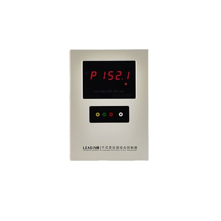
BWDK-3206H Temperature Controller of Dry BWDK-3206H
BWDK-3206A Temperature Controller of Dry BWDK-3206A
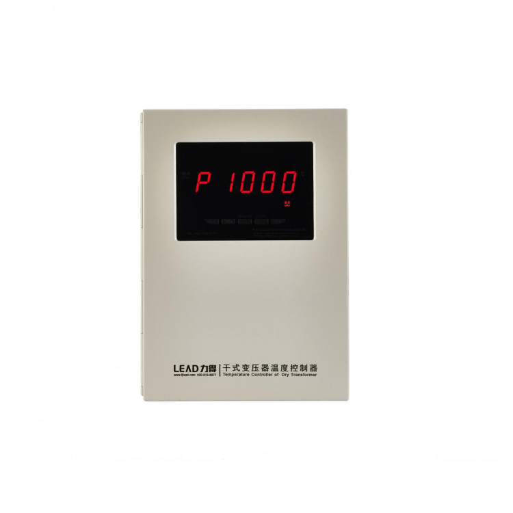
LD-B10-220 Temperature Controller of Dry LD-B10-220
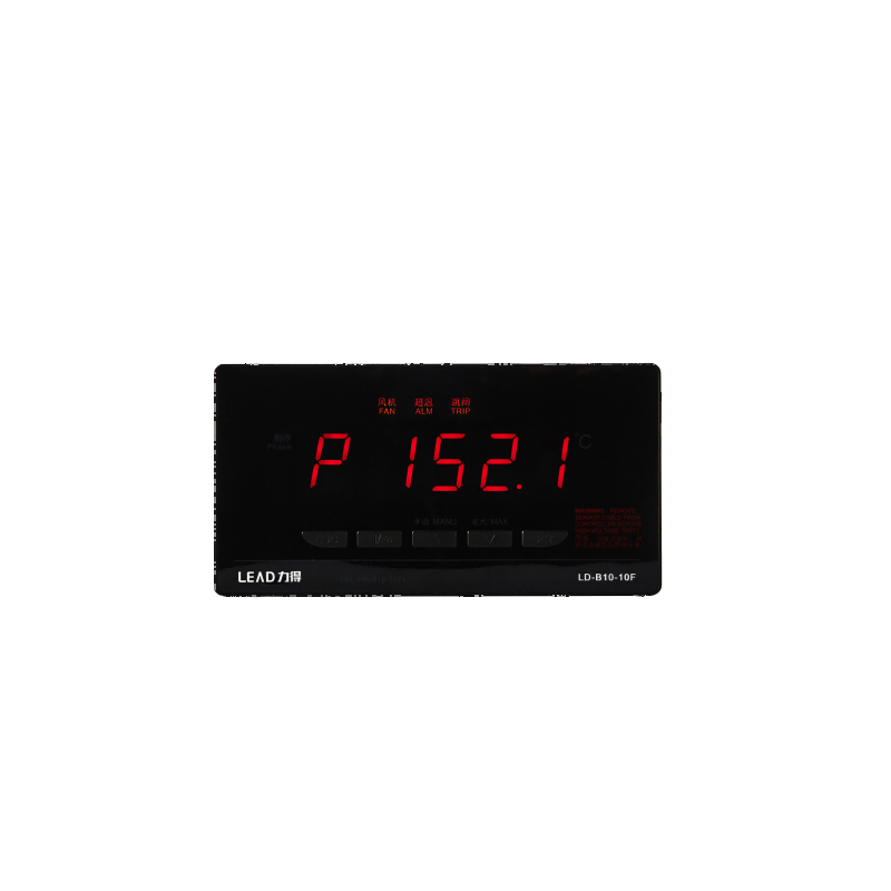
Temperature Controller of Dry LD-B10-10F